I’m working on a tool that automates the creation and placement of views on a sheet based on selected rooms. Basically, from the selected rooms, it creates a plan, RCP, and four interior elevations, and an axon, crops them to slightly larger than the room bounding box or plan boundary, then places them in a specified layout on a newly created sheet.
Because of the way the pilot project’s Revit model is set up (slabs in linked core and shell model), the interior elevations initially span multiple floors vertically, but the script reshapes the crop region using the bounding box of the associated room. After the views are created, but before placing on the sheet, all annotations are turned off to nullify the effect of having grids, levels, and sections outside the crop boundary during placement on a sheet. A series of vectors and relationships are used to locate each view on the sheet relative to either the sheet origin point or a previously placed view. A ‘diagonal’ vector for each view is calculated by taking the view bounding box max and min, subtracting them, diving by 2, then dividing by the view scale to get the center point of the viewport relative to a corner placement reference point.
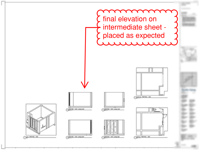
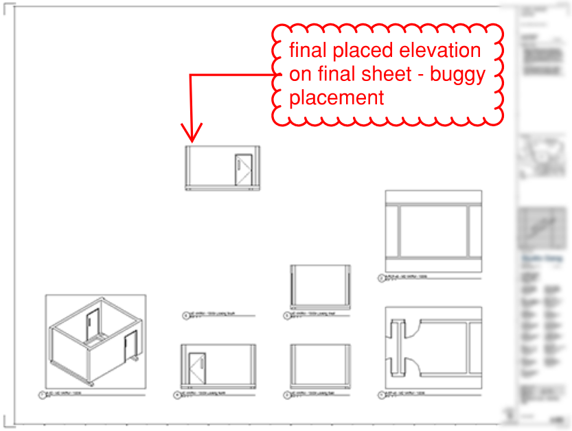
The issue that I’m having is with the placement of the final elevation on the final sheet. For whatever reason, all of the preceding elevations on other sheets are placed as expected, but the final elevation is placed as if it wasn’t cropped, and thus located much higher on the sheet than normal - see images below. In trying to debug by printing the values of different vectors at different points in time, it seems like the final elevation’s ‘diagonal’ vector always has a Y value significantly larger than all of the other views.
I’ve tried re-ordering the creation/placement of the cardinal directions, but it still happens to the last created elevation. If I change the looping of the view creation and placement on sheets, it can make it so that ALL sheets instead of the last sheet are similarly buggy, but with the current looping it only happens to the last sheet. (see comment a last ‘for’ loop This makes me think that somehow in the view creation / CropRegionShapeManager useage, when the loop is exited, something is not disposed or garbage collected correctly, and the crop region is only partially applied to the last elevation. (Being a self-taught Python programmer, I really have very little clue how garbage collection and element disposal are supposed to work…) I’ve tried manually disposing of different elements, but this doesn’t seem to have any effect.
Any ideas where this bug could be coming from?
Revit 2023
pyRevit 4.8.12
Code here for reference: Github Repo
(Please forgive incomplete commenting, commented out print statements etc - WIP code…)
If you clone the repo and test it out, make sure to rename the titleblock and view type variables.