Drafting View Work Plane Toggle & Spacing Setting

Hi, all.

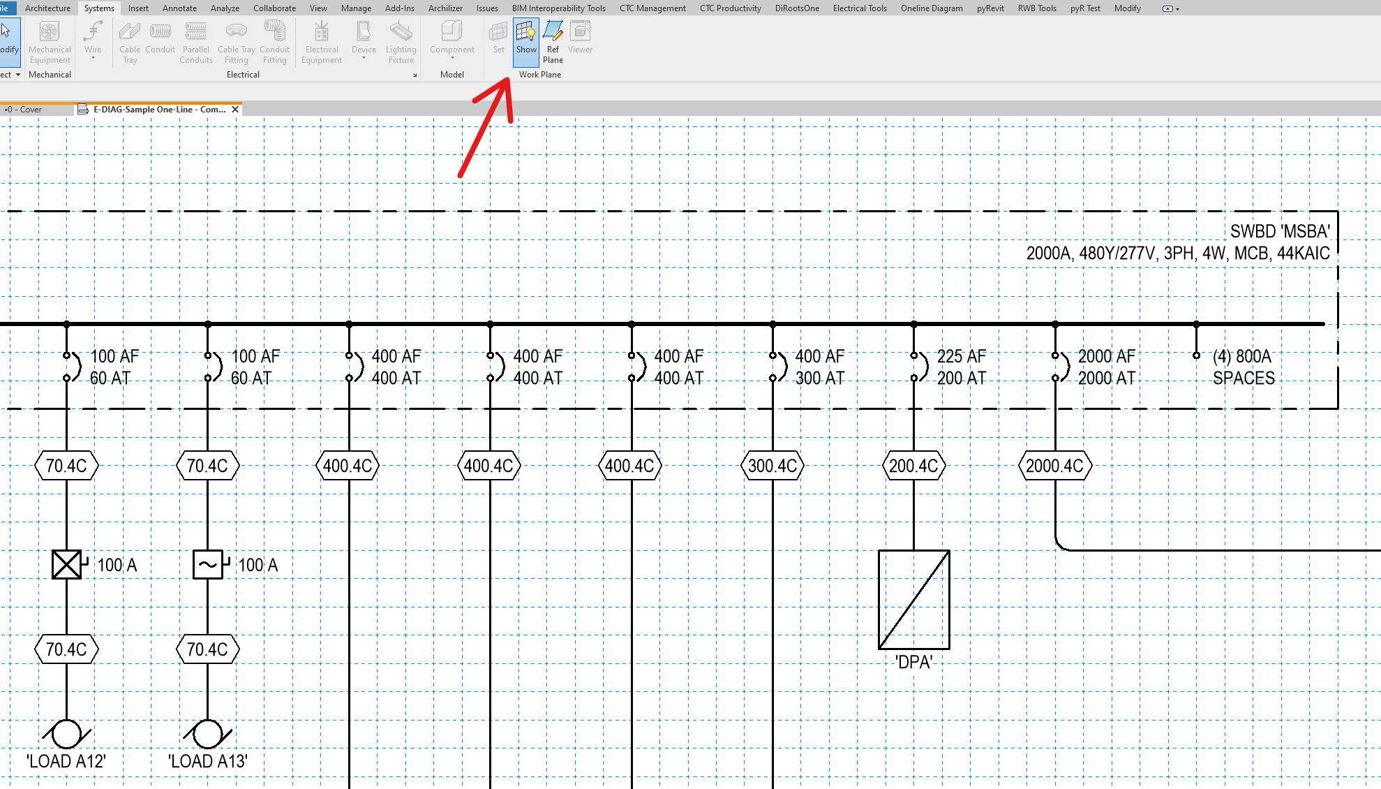
We are trying to write a script for a tool that runs in drafting views, which basically toggles the work plane on and off (the same as going to Systems tab > Work Plane panel > Show button), and also sets the spacing of the workplane to 0.2". We got the script below, which is simple enough but somehow won’t work:

# Import necessary libraries
from pyrevit import revit, DB

# Get the current document
doc = revit.doc

# Get the active view
active_view = doc.ActiveView

# Check if the work plane is visible
if active_view.ShowActiveWorkPlane:
    # If the work plane is visible, hide it
    active_view.HideActiveWorkPlane()
else:
    # If the work plane is hidden, show it and set the spacing to 0.2"
    active_view.ShowActiveWorkPlane()
    # TODO: set spacing to 0.2"

We get errors saying there’s no “scketchPlane” in the view, and other similar errors, depending on how we change the script. We’ve been going to the API docs to review methods, and it seems we are in the right track…

Could we get a hand on this script? If we get the toggling to work, could we also have it set the spacing to 0.2"? I looked around the API docs for something like that but couldn’t find methods that seem to do that…

Thanks in advance,

Edgar

Hi,
My guess is that drafting view do not have a workplane, even though they inherit Show and Hide Active Work Plane methods.

ShowActiveWorkPlane() method

The general code below would work in most cases, not in drafting views.

from pyrevit import revit, DB

doc = revit.doc

active_view = doc.ActiveView

with revit.Transaction('set active workplane'):
    # active_view.HideActiveWorkPlane()
    active_view.ShowActiveWorkPlane()
    # get workplane:
    wp = DB.FilteredElementCollector(doc,active_view.Id).OfCategory(DB.BuiltInCategory.OST_IOSSketchGrid).ToElements()[0]
    wp.get_Parameter(DB.BuiltInParameter.SKETCH_GRID_SPACING_PARAM).Set(1) # 1 is in decimal feet, like revit internal unit system

As a general rule, if the functionality is not available in the UI, it is not available in the API.

To further expand the discussion, the sketch grid is available in sheets where you place drafting view.
You would need to

  1. create or use the existing sketch grid of the sheet,
  2. activate it,
  3. set its spacing

Hi, Jean-Marc. Thanks first for always being available to help us here in this forum :+1:

I agree with the general rule - we probably wouldn’t pursue something like this unless it was part of the UI or user experience - which is just the thing - work planes are indeed available for the users on Drafting Views through the user interface:

It is very useful when you want to generate schematic drawings and have the content neatly spaced and more easily readable (and it looks much more professional anyway). Once we turn it on, it comes on with a generic spacing and so we have to then select the work plane (it’s selectable by clicking on its boundary/edges) and change its “Spacing” property to 0.2 inches. It would be ideal if we could have a button that does all that on the same tab with all of our schematic tools and symbols.

I tried employing some AI yesterday and got this, which also does not work but might help in tuning down on something that might (not sure). Btw, AI might have promises, but I much prefer human-generated code, or at least human-fine-tuned code, which is why I come to you here in the forums:

import clr
clr.AddReference('RevitAPI')
clr.AddReference('RevitAPIUI')

from Autodesk.Revit.DB import Document, Transaction
from Autodesk.Revit.UI import UIApplication

# Function to check if the work plane is visible
def is_work_plane_visible(uiapp):
    return uiapp.ActiveUIDocument.GetOpenUIViews()[0].WorkPlaneVisibility

# Function to toggle the work plane visibility
def toggle_work_plane(uiapp, visible):
    for view in uiapp.ActiveUIDocument.GetOpenUIViews():
        view.WorkPlaneVisibility = visible

# Function to set work plane grid spacing
def set_work_plane_grid_spacing(doc, spacing):
    with Transaction(doc, "Set Work Plane Grid Spacing") as trans:
        trans.Start()
        doc.ActiveView.SketchPlane.GetPlane().GridSpacing = spacing
        trans.Commit()

# Main function
def main():
    # Get the active UIApplication
    uiapp = UIApplication(__revit__.Application)
    doc = __revit__.ActiveUIDocument.Document

    # Check if the work plane is visible
    if is_work_plane_visible(uiapp):
        # Work plane is on, toggle it off
        toggle_work_plane(uiapp, False)
    else:
        # Work plane is off, toggle it on and set grid spacing
        toggle_work_plane(uiapp, True)
        set_work_plane_grid_spacing(doc, 0.2)  # Grid spacing set to 0.2 inches

# Execute the main function
main()

Again, thanks in advance,

Edgar

Edgar,

While researching this problem I found this thread. Always glad to share my solutions with another lost soul. I did figure this out (AI Assisted coding).

This extracts the object face of the work plane. Using Revit Snoop I Was able to see that corresponded to the offset of the grid spacing. I simply move that to the origin. One would still need to use the UI handles to make the work plane grid extents bigger or smaller.

You didn’t bring it up, but for anyone else who happens to be reading later, I find it helpful to use 5/32” as my P&ID grid since that aligns with Revit’s internal “Nudge” distance (Shift+Arrow key)
Depending on zoom level, the Nudge distance is as follows:
Nudge 1/128” → 1/64” → 1/32” → 1/16”
Shift+Nudge 5/64” → 5/32 → 5/16 → 5/8

import clr
clr.AddReference('RevitAPI')
clr.AddReference('RevitAPIUI')
clr.AddReference('RevitServices')

from Autodesk.Revit.DB import *
from RevitServices.Persistence import DocumentManager
from RevitServices.Transactions import TransactionManager

SPACING = (5.0 / 64.0) / 12.0 # 5/64" in decimal feet

try:
doc = DocumentManager.Instance.CurrentDBDocument
active_view = doc.ActiveView

grid = FilteredElementCollector(doc, active_view.Id)\
.OfCategory(BuiltInCategory.OST_IOSSketchGrid)\
.ToElements()[0]

opt = Options()
opt.View = active_view
geom = grid.get_Geometry(opt)

origin = None
for obj in geom:
if hasattr(obj, 'Faces')and obj.Faces.Size > 0:
origin = obj.Faces[0].Origin
break

ogs = OverrideGraphicSettings()
ogs.SetSurfaceTransparency(100)
ogs.SetProjectionLineColor(Color(220, 230, 240))

TransactionManager.Instance.EnsureInTransaction(doc)
ElementTransformUtils.MoveElement(doc, grid.Id, XYZ(-origin.X, -origin.Y, 0))
grid.LookupParameter("Work Plane Grid Spacing").Set(SPACING)
active_view.SetElementOverrides(grid.Id, ogs)
TransactionManager.Instance.TransactionTaskDone()

OUT = grid

except Exception as e:
TransactionManager.Instance.ForceCloseTransaction()
OUT = None

1 Like

I’ve also noticed it helps to override the element’s appearance in the view and encourage users to disable “Select Elements by Face” from the bottom right selection filter tray.

Thank you for coming back to this post and providing the code, @Alex.K! I had pretty much given up, since I couldn’t find a solution.

What you did looks very promising, but when I run the above code nothing happens on my end: no errors messages nor any workplane grids show up… am I perhaps missing something? I try zoom extents tool, but still nothing.

PS.: I am using Revit v2025

Only solved one of your problems, not the other. I am not able to show/hide the grid — that’s still up to the user or whoever creates the view. My script runs in a drafting view where the plane has been turned on already. It can’t auto-size it either. Thats the bit I probably worked at the longest and couldn’t solve. I’m running it as a Dynamo Python node in Revit 2026.

Extract the active view grid element by filtering to the OST_IOSketchGrid element.
Extract the grid’s face to find the Origin.
Move the grid origin to 0,0 — it does not move the workplane itself but ensures the grid is where it should be. Like sliding a model pattern.
Override in view to a light gray and transparent so it’s less intense. Did you find any other way to control its appearance? I couldn’t.

For our purposes I can use this script to create template views and verify that existing haven’t been mucked with. Then, a designer can show/hide the workplane as needed. Since I use a very fine grid of 5/32" it seems okay to leave it on all the time. It disappears when you zoom out and doesn’t snap. (Good). Note designers should disable the “Select objects by Face” selection filter in the bottom right so they don’t accidentally select and move the work plane.

I’m very happy with how this grid snapping ends up working. While zoomed out you’re not constrained at all, and when zoomed in you get a good snap. Since I’m relying on Shift+Arrow nudge as a replacement for Autocad’s “Stretch,” it’s easy to revise single line diagrams while zoomed out and easy to place stuff on the grid while zoomed in. As long as folks use the shift+Arrow key to stretch, everything stays griddy.

Sorry for the long post, but as a final aside in my version of the script I created a filter that did the graphic styling of the workplane instead of override in view. I didn’t like that when duplicating the view it would reset my overrides. Curiously you can create this sketchy filter applied to the Internal workplanes category even though you can’t do it in the UI. It works great, but if you go to the Visibility/Graphics “Filters” tab in the view Revit crashes :slight_smile: . I’m sure there’s it’s bad practice to leave that but also there’s no situation on earth where someone should be editing the V/G of a drafting view (right?) I’d report this bug but I don’t want Autodesk reps laughing me off ‘well what the heck did you think would happen’.

1 Like

Thanks, @Alex.K, that’s a good explanation. Unfortunately I am not familiar with Dynamo Python nodes (I haven’t used Dynamo at all so far, and yeah, I know, I should learn it - maybe one day).

This is an odd task that looks like it should be easy to accomplish through a simple pyRevit script - the button to show/hide is there so we can already toggle it manually, it works, and the properties of the workplane are all available when we display it, so why can’t we do it all through a script? The fact that the solution to this apparently simple problem has eluded us for so long is baffling.

Still, kudos for you for finding a workaround that helps on your end - as I see it, it wasn’t easy/quick :+1:

Regarding how to change the style of the grid, I do the same thing you did through override in view - I couldn’t find a setting anywhere on Revit that controls that globally.

All the best,

Edgar